Simulator Stability Improvements: GSoC'23 Final Report

This blog post is a report of all the features implemented, goals accomplished, and future plans in the Simulator Stability Improvements Project as a part of GSoC 2023 at CircuitVerse.
About My Project
My project is focused on enhancing the stability and reliability of simulation environments. It aims to resolve common issues such as crashes, slow performance, and unexpected behavior that can disrupt the simulation experience for complex circuits.
Project Goals and Implementation
- Fix Data integrity issues: The goal was to identify and fix the data integrity issues that were causing data corruption for users.
- Implement a debug interface on the simulator: The aim was to implement a debug interface on the simulator that would give us more information about the simulator’s state from the dev console, allow us to load circuits, and dynamically load and unload parts of the circuit.
- Implement a safe recovery from simulator crashes: A safe recovery flow that ideally lets the user to restore a previous non-erroneous state of the circuit.
- Make a better system for high impedance (X) values: In the previously implemented system for high-impedance values, there were some shortcomings that needed to be rectified.
Data integrity issues
I’ve found and successfully addressed four issues in this context:
Changed the Implementation of Priority Queue using a Heap Data Structure
In the previous approach, the priority queue was managed using an array-based method with explicit sorting to maintain priority order, resulting in a complexity of O(n^2). With the new implementation, the ‘add’ method employs heapify-up to determine the correct position for inserting an element. The ‘remove’ method utilizes heapify-down to uphold the heap property after an element is removed. These heapify operations exhibit logarithmic time complexity (O(log n)), significantly enhancing the efficiency of the binary heap for priority queue management compared to the linear approach. Both implementations achieve the same goal of arranging elements based on timestamps (priorities). However, the new implementation is an improvement, utilizing a binary heap data structure that substantially improves performance for larger event queues due to its efficient O(log n) time complexity for insertion and removal operations.
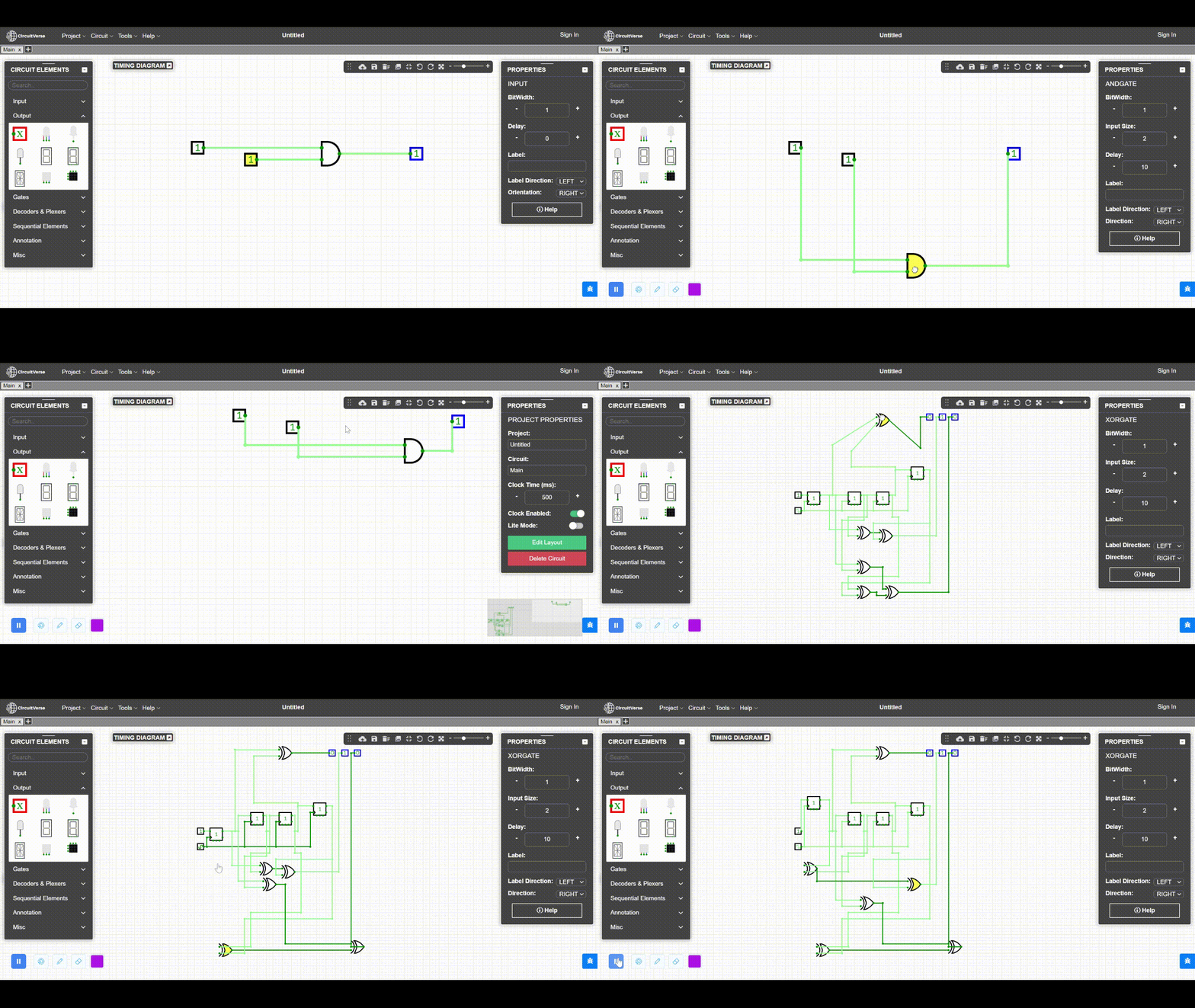
Disrupted Connected Wires when Moving a Component
Understanding the functionality of this feature is best facilitated through visualization. For this, a demo video has been attached for reference. Essentially, improvements have been made to the wiring. Now, when components are moved, their connections are less likely to be disrupted. Previously, even slight movement of components resulted in tangled wires, but the new implementation greatly mitigates this issue. This enhancement is poised to significantly benefit users.
Enabling Delay of 0 on Non-Input/Output Components
I’ve rectified the saving of the ‘zero’ delay value for components. With this fix, components within the circuit can now be set to a delay of 0 and subsequently saved accordingly.
Persistent Error Messages After Issue Resolution
I had observed on Slack that many users reported this issue. I have implemented a fix for this. In the past, when the canvas displayed an error message and a user clicked on it multiple times in quick succession, the message would persist even after resolving the error. I successfully resolved this problem, ensuring that error messages are now properly removed once the issue is addressed.
Demo

| Pull Requests |
|---|
| Change the implementation of the priority queue to use a heap data structure |
| Moving a component messed up the connected wires |
Debug interface on the simulator
I have implemented 4 sub-features within it, which will make the circuit debugging process easier than before.
A way for the circuit to recover from errors if the erroneous component is removed
In this, I have implemented a state machine. So, Now whenever an uncaught exception error occurs in the simulator, the state of the simulator transitions from normal to an error state. All the tabs from which the user can add new component will remain hidden until the simulator is in the error state. Once the user removes the erroneous component, all the tabs become visible again, and the simulator returns to the normal state.
Identify the currently selected component and modify that component’s object
For this feature, I’ve implemented two functions. The first function is ‘getCurrentlySelectedComponent’, which returns the currently selected component. The second function is ‘getAllSelectedComponent’, which returns all the selected components if multiple elements are selected together in the circuit. Then, I’ve implemented the ‘modifyCurrentlySelectedComponent’ function. This function takes two parameters: the property of the currently selected component that needs modification and the modified value. It then updates the specified property in the global scope.
In case of the ‘Simulation Stack Exceeded’ error, a way to find the components that are being added to the simulation stack an unnaturally large number of times
To address this, I’ve introduced a ‘detectCycle()’ function. It enables the identification of nodes within the circuit that form cyclic paths, and highlighting them in the simulator. Using the depth-first search (DFS) algorithm, I’ve employed this function to locate all the nodes involved in cycles. The function returns an array of nodes forming cyclic paths, which makes it possible to detect the nodes contributing to the ‘simulation stack exceeded’ error.
It should also expose helpful functions
In this task, I’ve implemented several beneficial functions
- loadCircuit: This function loads a circuit using circuit data.
- previous: A function to retrieve the previous stable state of the circuit.
- highlightNodes: A function that highlights nodes in the currently selected circuit. It takes node IDs as parameters to indicate which nodes should be highlighted.
- findNodeIndexById: This function finds the index of a node in globalScope.allNodes. It takes a node ID as a parameter and returns the index.
These advancements undoubtedly enhance the debugging experience and provide valuable tools for managing and troubleshooting circuit-related issues.
Demo
| Pull Requests |
|---|
| Implemented state machine for simulator |
| Added helpful functions for debugging of circuits |
Safe recovery from simulator crashes
Previously, When the simulator crashed, all the circuit data would get lost. Losing all that work was disheartening. To address this issue, I worked on implementing a solution for recovering the circuit data from simulator crashes.
To achieve this, I have added an autosave function that automatically saves the current circuit data at intervals of 3 seconds. So, whenever a simulator crash occurs, the autosave function preserves the data of the last stable state. When the user reloads the page, a message appears on the canvas: “We have detected an unexpected simulator crash. Don’t worry, we have recovered your project. Access it using Project->Recover.” The user can then go to “Project->Recover Project” and restore the circuit. This secure recovery process allows the user to retrieve a previous non-erroneous state of the circuit.
By implementing this simulator crash recovery mechanism, users can avoid losing their work and retain the ability to restore their circuits after an unexpected crash.
Demo
| Pull Requests |
|---|
| Implemented safe recovery from simulator crash |
Better system for high impedance(X) values
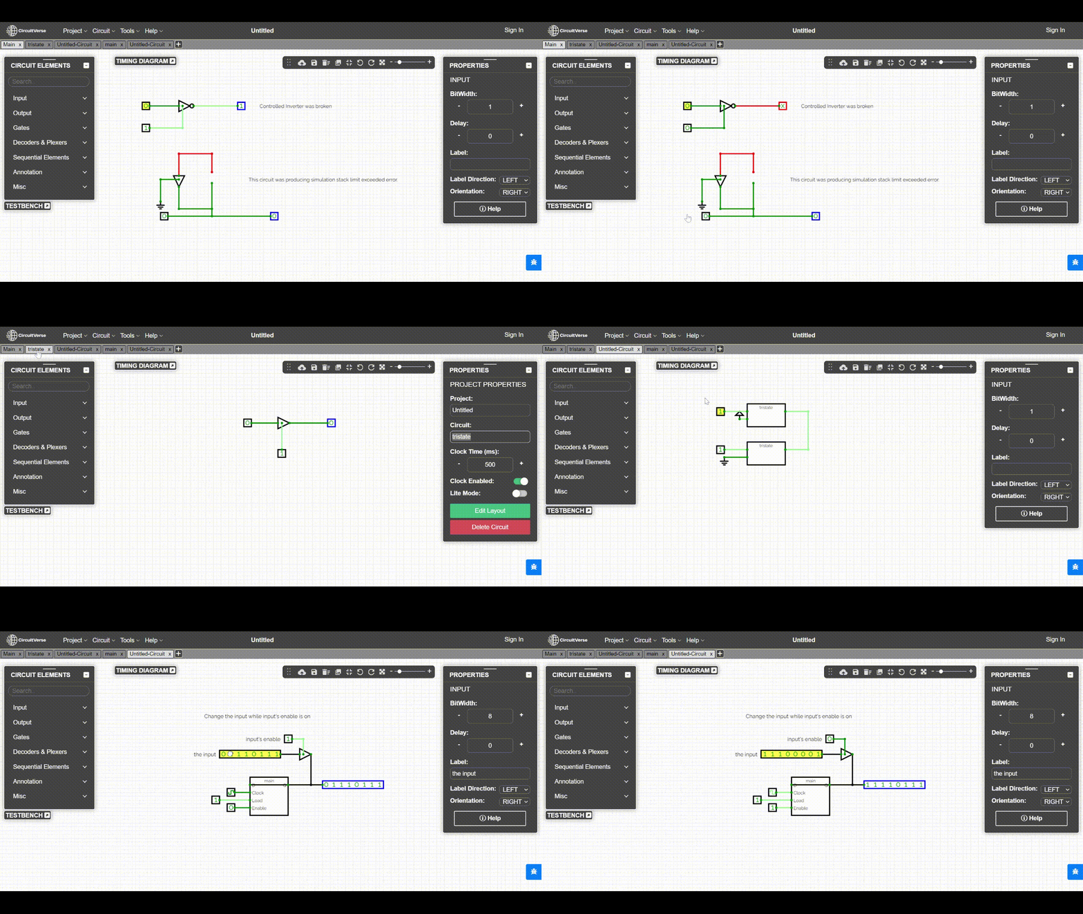
In the CircuitVerse simulator, there are two circuit elements, Tristate and Controlled Inverter, that exhibit high impedance behavior. Previously, the Controlled Inverter was broken, and the Tristate had some issues.
In this task, I attempted to fix the issues with both of these circuit elements. First, I addressed the functionality of the Controlled Inverter and also fixed the incorrect test associated with it. I focused on identifying and resolving issues related to the Tristate element. Then, there are several open Tristate-related issues in the primary code base repository, I attempted to address all of them.
Demo

| Pull Requests |
|---|
| Better system for high impedence values |
Learnings
- Gained an understanding of the optimal approaches for code composition.
- Addressing data integrity issues, recovery mechanisms and error propagation deepened my understanding of error-handling strategies.
- Gained a deep understanding of simulation environments, debugging tools, and techniques to enhance the stability of complex systems.
Future Work
I have attempted to resolve the data integrity issues I encountered. However, if there are any circuit reports in the future on the Slack channel containing data integrity issues, they will still be addressed. Therefore, please continue to report any issues you come across on the simulator.
Blog posts
I’ve created comprehensive blog posts for each phase of GSoC, aiming for them to be both engaging and informative.
| Blog Posts |
|---|
| Coding Period Week 1 + 2 |
| Coding Period Week 3 + 4 + 5 |
| GSoC'23 Phase 1 Report |
| Coding Period Week 7 + 8 |
| Coding Period Week 9 + 10 |
| Coding Period Week 11 + 12 |
Conclusion
It’s true that time flies. It feels as though it was just 2-4 days ago that the GSoC coding period began, and now it has come to an end so quickly. It’s astonishing how swiftly time has passed by. The experience was filled with moments of intense concentration and dedication.
However, I am extremely happy that my project has been successfully completed. And,I would like to express gratitude to my mentors Pulkit Gupta, Ruturaj Mohite, Pranay Simejia, and Satvik Ramaprasad. Their invaluable feedback on my progress and unwavering support have played a pivotal role in this journey.